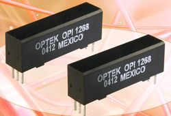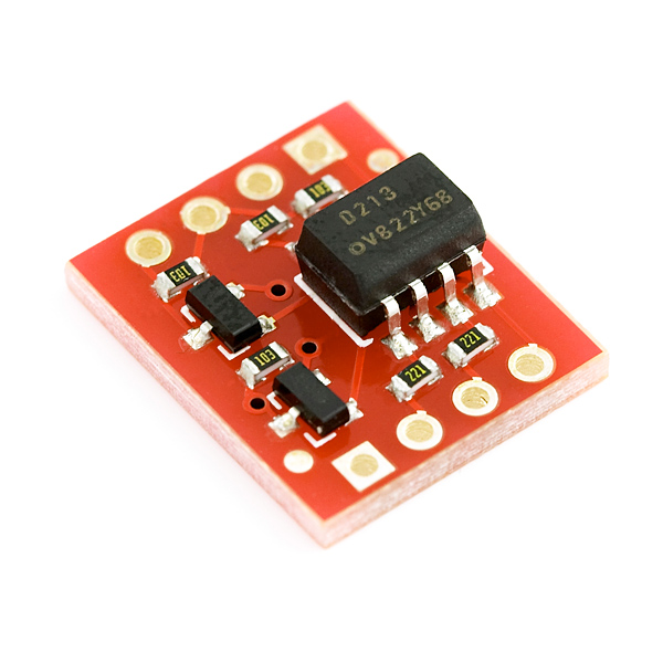

The output is a differential analog signal amplified by either 8.1x or 16.2x. The Si8920 isolated amplifier utilizes our proprietary isolation technology and supports up to 5.0 kVrms withstand voltage per UL1577. Exceptionally high common mode transient immunity enables the Si8920 to deliver accurate measurements even in the presence of high power switching, such as in motor drive system or inverter applications. Low offset and gain drift ensure accuracy is maintained over the entire operating temperature range. The very low signal delay of the Si8920 allows control systems to respond quickly to fault conditions or changes in load. Our amplifier family offers low voltage and differential input while providing higher performance, reduced variation with temperature and age, tighter part-to-part matching, and longer lifetimes compared to other isolation technologies. The Silicon Labs Si8920 is a galvanically isolated analog amplifier ideal for measuring voltage across a current shunt resistor or for any place where a sensor must be isolated from the control system. Where do I find the best Analog Isolators for my needs?

So even though there are two grounds and different voltages at each ground, there is no current flow. When the conductive path between the differential voltages is broken, a current cannot form. So what can be done? Use a signal isolator to “break” the galvanic path between the two grounds. From a practical standpoint, you cannot reach into the earth and regulate the voltage at these permanent ground points. The process which, in turn, is in physical contact with the ground. It’s also possible that the ground exists because the instrument is in physical contact with The ground may be required for the safe operation of an electronic device. Why? Because you cannot always control the number of grounds, and it is often impossible to just “lift” a ground. The challenge is, the first and second conditions are not plausible candidates for elimination. To remove the ground loop, any one of these three conditions must be eliminated.

There is a galvanic path between the grounds.The grounds are at different potentials.This current path, known as a ground loop, is a very common source of signal inaccuracies.Ī ground loop forms when three conditions are present: When this happens, an additional and unpredictable amount of current is introduced into the loop, which distorts the true measurement. But when the voltages (V) at the two ground points are different, a circulating, closed current (I) path is formed by the copper wires used for the 4-20mA signal and the ground. The loop in question may be as simple as a differential pressure (DP) transmitter sending a 4-20mA measurement to a receiver, such as a recorder.

However, it was soon discovered that when 4-20mA (or other DC) signal wires have paths to ground at both ends of the loop, problems are likely to occur. Electronic transmitters were quickly replacing their pneumatic predecessors because of cost, installation, maintenance and performance advantages. The need for signal isolation began to flourish in the 1960s and continues today.


 0 kommentar(er)
